CO2 Laser Power Supplies
2.1 GENERAL
After unpacking, general inspection and preliminary check-out procedures should be performed to ensure that the unit is in proper working order. If it is determined that the unit has been damaged, the carrier should be notified immediately. Contact LIC directly:
LIC Engineering
3735 Coffey Ln.
Santa Rosa, CA 95403 USA
Tel: (707) 575 8821
Fax: (707) 526 3905
Email:tech@licengine.com
2.2 INSPECTION
Check for damage incurred during shipment as follows:
- Inspect unit case for cracking, bending, and other obvious signs of damage.
- Check water inlet & outlet for bending.
2.3 OIL FILLING (for 25KW/50KW OEM products only)
Loosen all screws on the top cover of H.V. container(oil container). Pull up whole body of the power supply from the H.V. container with care ( not to damage oil seal). Pour the insulating oil supplied with a separated oil can into the H.V. container up to the line marked. When the oil level reaches the marked line, slowly put the whole power supply back to the H.V. container. Be careful that no H.V. components touch the open edge of H.V. container. Tighten all the screws for the top cover of H.V. container.
2.4 OUTPUT WIRE CONNECTIONS
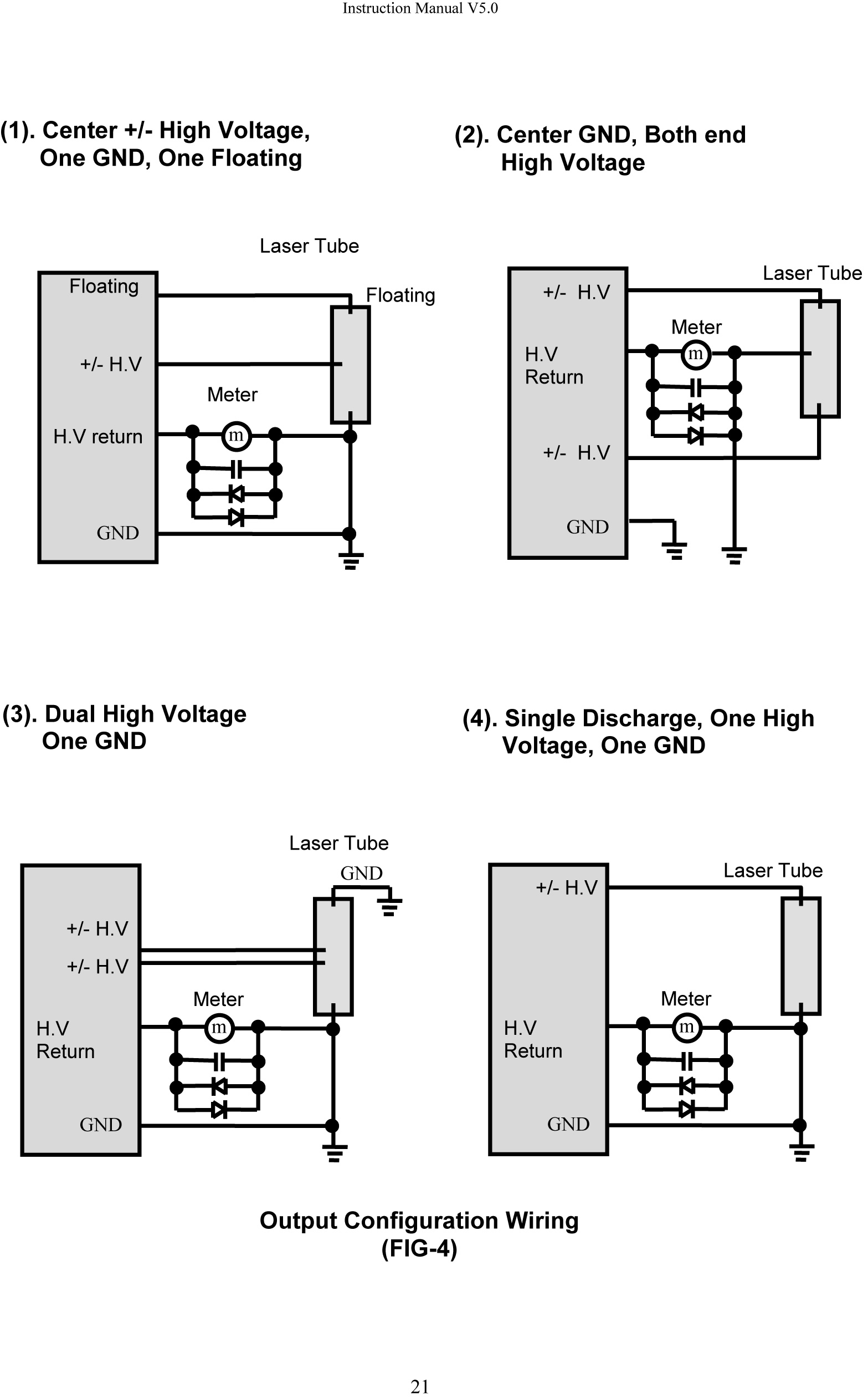
Refer to the following wiring diagram of Fig-4.
CAUTION:
Do not put a resistor in a H.V return line. H.V return line potential must be less than 1 V reference to GND in order for the error amplifier inside the unit to work properly
2.6 WATER LINE CONNECTION
Any tap water can be used. Connect cooling water lines to the power supply firmly. After connecting the line, apply the water pressure that is expected in that line. Confirm that the water temperature is within the specification for the unit and if there is no water leakage at the connections. Lic’s power supply does not require much water to flow. Cooling water electrical potential is at the ground level.
Ultra Stable Laser System CRG-1200
Laser Diode Drivers – LD-series
2.1 GENERAL
After unpacking, general inspection and preliminary checkout procedures should be performed to ensure that the unit is in proper working order. If it is determined that the unit has been damaged, the carrier should be notified immediately. Contact LIC directly:
LIC Engineering
3735 Coffey Ln.
Santa Rosa, CA 95403 USA
Tel: (707) 575 8821
Fax: (707) 526 3905
email: info@LicEngine.com
2.2 INSPECTION
Check for damage incurred during shipment as follows:
1) Inspect unit case for cracking, bending, and other obvious signs of damage.
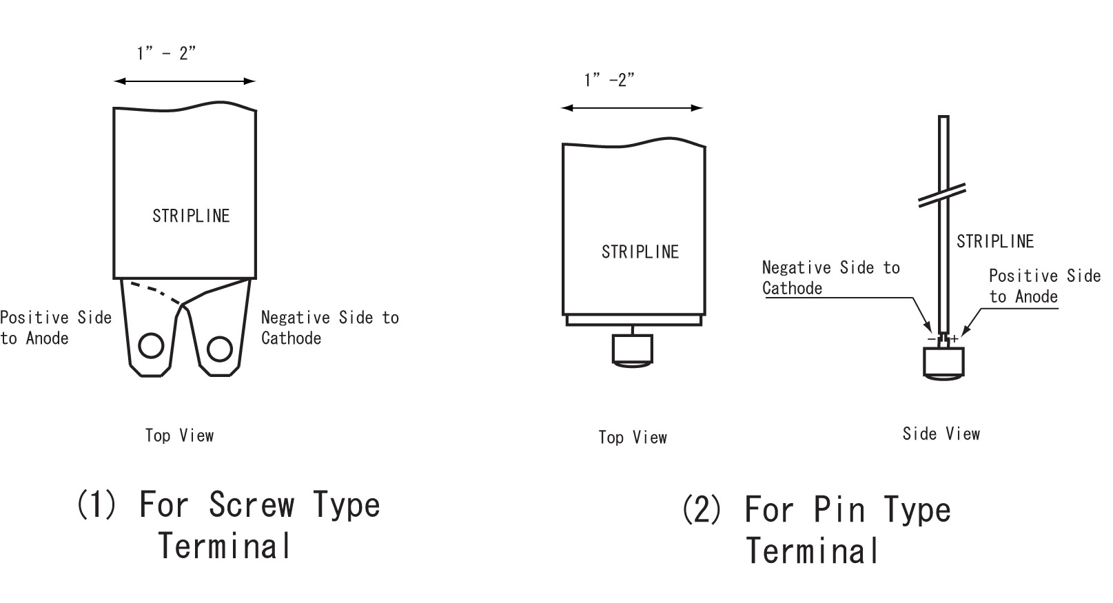
2.3 OUTPUT STRIPLINE CONNECTIONS
Connect the stripline to the load (Laser Diode) using a soldering iron, or screws.
The physical distance between the load and tip of the stripline must be as short as possible.
Do not use any extra wires to connect between the strip line and a Laser Diode.
USING SUCH EXTRA WIRES WILL INCREASE A RISE AND FALL TIME DRAMATICALLY.
PLEASE REFER TO LSP-XXXX-XX MANUAL FOR DETAIL:
HTTP://WWW.LICENGINE.COM/SUPPORT/PDF/MANUAL-LSP1B.PDF
Formula is Trise-time=LxdI/Vo,
where Vo: the maximum output voltage of the unit, dI: Current increment within the time of Trise-time, L: Total inductance (LD-pin inductance plus internal lead wire inductance, plus external lead wire inductance).
Example 1):
500A load current, Total inductance=100nH, and Output voltage =50V, then, the fastest rise time T is only 1 us.
Example 2):
500A load current, Total inductance=100nH, Output Voltage =300V, then the fastest rise time will be: 170ns-200ns.
2 1
Instruction Manual V2.2
Refer to 3.1.3 RISE TIME, LOAD IMPEDANCE, AND OUTPUT VOLTAGE
THE FORWARDING VOLTAGE OF CONNECTED LD MUST BE CLOSE TO THE OUTPUT VOLTAGE SPECIFIED WHEN THE UNIT IS ORDERED.
IF THE LD VOLTAGE IS MUCH LOWERED THAN THE VALUE SPECIFIED, THE RISE TIME OF OUTPUT CURRENT BECOMES SLOW.
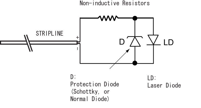
IN THIS CASE, THE SERIES RESISTOR CAN BE CONNECTED AS SHOWN IN THE FOLLOWING PICTURE.
THIS SERIES RESISTORS SHOULD BE VERY LOW INDUCTANCE TYPE AND MUST SATISFY THE EXPECTED PEAK CURRENT, VOLTAGE AND AVERAGE POWER.
Refer to 3.1.3 RISE TIME AND LOAD IMPEDANCE, OUTPUT VOLTAGE for detail.
Contact factory if user can not find such resistors. Lic has a wide range of non-inductive resistor of which power ranges from 5W (air cooled) to 5KW (water cooled).
To protect user’s LD from a reverse current, it is good idea to use a protection diode connected in parallel with the LD as follows. The reverse current will increase when the load inductance is increased. Check with a current monitor waveform if the reverse current is within safe area.
2.4 INTERLOCK CONNECTION
Connect Interlock connector to the unit. Make sure the end of wire is connected together(Shorted).
If Interlock input is not shorted, the unit becomes Fault condition.
This wire can be used as a remote switch to activate/deactivate the load current.
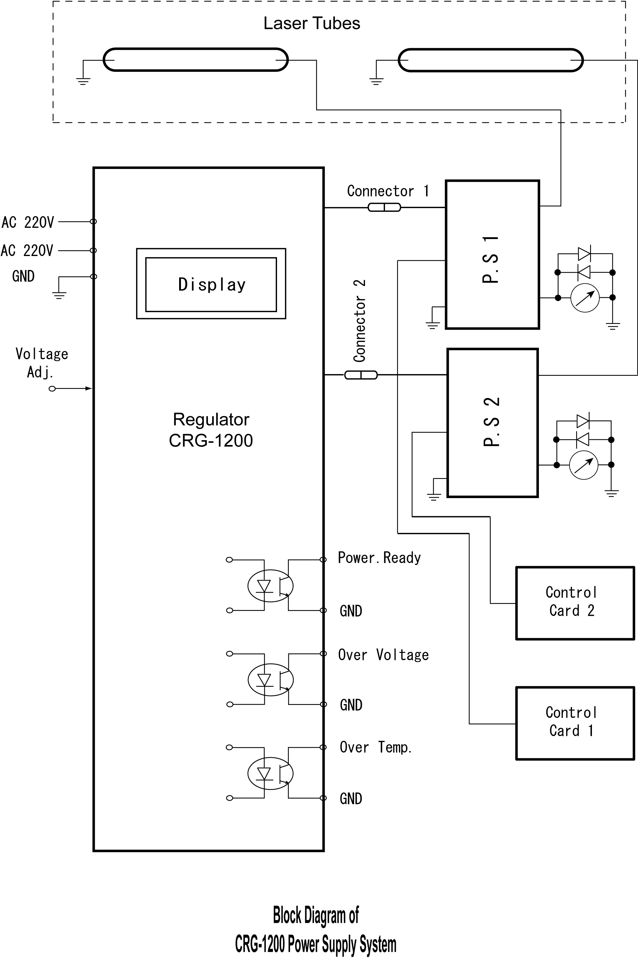
2.5 BLOCK DIAGRAM OF THE UNIT
2.6 AC LINE CONNECTION
Confirm AC GND(Earth GND) is connected to the power supply GND.
2 3
Instruction Manual V2.2
Confirm that AC line voltage is proper for the unit ordered, and AC power to the unit is still off. The standard center voltages are:
100/115/208/220, Single phase/three phase, +/- 10%
2.4 Output Configuration
Laser Diode Drivers-LSP-series
Check for damage incurred during shipment including the unit case for cracking, bending, and other obvious signs of damage.
2.1 POWER CORD CONNECTIONS
Connect the AC power cord supplied to LSP-EVBD. Make sure GND wire is
connected to the GND terminal on the board.
2.2 LASER DIODE CONNECTION
Connect the laser diode to the one of each output. Be careful for the lead
wire inductance:
If the lead wire is not short enough, the peak current is lowered and the
rise time becomes slow.
Refer to the following famous formula:
V(v)=L(nH)xdI(A)/dt(ns)
Where, V=voltage across the lead wire (V), L=lead wire inductance (nH),
DI=peak diode current (A), dt=rise time (ns)
Depends on the laser diode you use, you may need to shape the end of
stripline. You can cut a copper plate of the stripline with a regular scissors to
shape you desire. Refer to the following section in this manual.
Instruction Manual V2.0