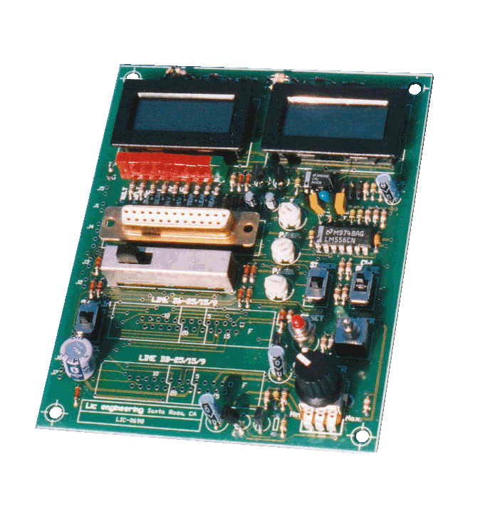
Interface Card for CSF-25000 series
- Daisy Chain Connection
- Optically Isolated
- H.V Voltage & Current Monitoring
- Line/Local Switch
- Displayed All Status Signals
| Pin Assignment: Connector: D-sub 25P male | ||
| 1 | REST | Input signal to reset FAULT condition |
| 2 | +5V | DC power for the internal circuit of power supply |
| 3 | GND | +5V DC ground |
| 4 | LASR | Input signal enables power supply either ON or OFF |
| 5 | RAMP | Input signal to activate RAMP signal |
| 6 | HVON | Output signal indicates H.V output voltage existing |
| 7 | HVCR | Analog output signal corresponding to total H.V current |
| 8 | HVLT | Analog output signal corresponding to H.V output voltage |
| 9 | TEMP | Output signal indicating over temperature failure |
| 10 | SWOC | Output signal indicating over current failure in primary circuit(#1) |
| 11 | CWPL | Input signal to activate CW or PULSE mode |
| 12 | HVOV | Output signal indicating H.V over voltage failure |
| 13 | HVOC | Output signal indicating H.V over current failure |
| 14 | REDY | Output signal indicates power supply is ready for H.V output |
| 15 | POWR | Analog input to control H.V current |
| 16 | FULT | Output signal indicates power supply is in fault condition |
| 17 | DEST | Output signal indicating over current failure in primary circuit(#2) |
| 18 | GDD | Power GND for external circuit |
| 19 | SIMR | Input signal to activate simmer mode |
| 20 | SIGG | Analog GND |
| 21 | VDD | DC power for external circuit |
| 22 | PWFL | Output signal indicating phase failure |
| 23 | WVFM | Analog signal showing SW current |
| 24 | LEAK | Output signal indicating over H.V leakage current |
| 25 | ENBL | Input signal enables power supply ON state |
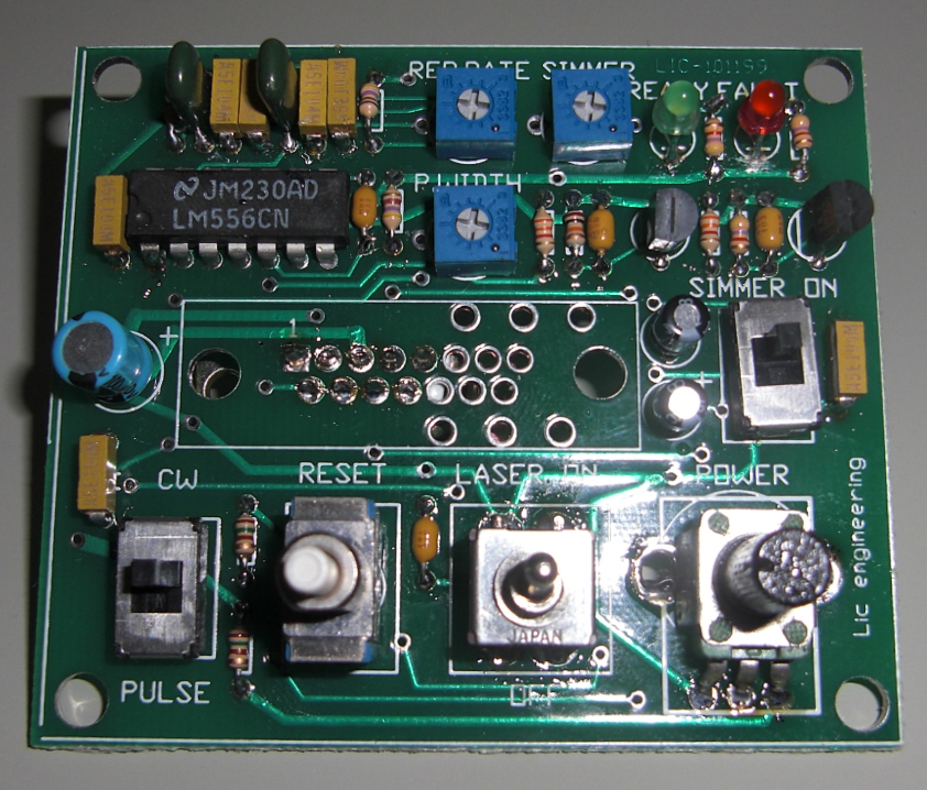
Interface Card for CPF-600/1000 & CSF1700/2500/3500/5000/8000 series

(Interface Card)
| Pin Assignment: Connector: D-sub 9P & 15P male | |||
| 9P | 15P | ||
| 1 | 1 | RESET | Input signal to recover from a fault condition. |
| 2 | 2 | +5 | DC power used inside circuit of power supply. |
| 3 | 3 | GND | DC power ground |
| 4 | 4 | LASER | Drive signal enables power supply to be either ON or OFF. In Pulse mode, a modulated pulse train will be inputted. |
| 5 | 5 | CW/PULSE | Input signal to activate CW or PULSE mode. |
| 6 | 9 | READY | Output signal indicate that power supply is ready for use. |
| 7 | 10 | POWER | Analog signal to control output current |
| 8 | 11 | FAULT | Output signal indicates that protection circuit inside power supply is activated. |
| 9 | 12 | SIMMER | Input signal to activate simmer mode. |
| Option: | |||
| 6 | H.V. 1 | Analog signal proportional to H.V current. | |
| 7 | H.V. 2 | Analog signal proportional to H.V voltage1. | |
| 8 | H.V. 3 | Analog signal proportional to H.V voltage2. | |
- Control Signal (extracted from Manual)
- 1.4 CONTROL SIGNALSLic’s laser power supplies use 9, 12, and 25 signals to control and monitor the power supply. These signals are completely isolated from an internal main AC line and GND line is connected to system ground (earth GND). In the following chapter, only 12 signals are described. The remaining signals will be explained in a separate MANUAL attached with a specific unit. The control signals are active-high logic as described below:.
- 1.4.1 LASER signal (INPUT) for all modelLaser signal controls output(s) of the power supply to be either ON or OFF. In Pulse mode, a modulated pulse train will be inputted. Whenever LASER is high, the power supply will produce a high voltage from its output.CAUTION:
If LASER signal is high during starting period of the power supply, high voltage output will appear suddenly as soon as READY comes. This could be dangerous under certain conditions. To prevent such accidental high voltage, keep LASER off before applying AC power to the power supply. - 1.4.2 CW/Pulse signal (INPUT) for CPZ-series, and CSF-25000/50000 onlyThis signal is used to select either CW mode or Pulse mode. When this is high, the unit operates in CW mode, and when it is low, the unit operates in Pulse mode. While the unit is operating, do not change this signal. It may cause a FAULT condition.
- 1.4.3 POWER signal (INPUT) for all modelsAnalog signal to control laser head current both in CW and Pulse mode.
Even in Pulse mode, the POWER signal will control an average H.V.. pulse current. - 1.4.4 RESET signal (INPUT) for all models except CPZ-seriesTo reset an activated protection circuit and to recover from the fault condition, this signal must be on and then off. The unit starts to restore not at the rising edge of RESET signal(ON edge) but the falling edge (OFF edge). If the fault is caused by a temporary reason (that is, the fault reason is already removed before sending RESET), the unit will be restored to a previous operating condition as soon as RESET signal comes to the OFF edge. But the fault condition exists, the unit may operate for a short time until protection circuits detect the fault condition again. If the unit keeps showing a fault after several resets, do not try resetting again. This could harm the unit.SECTION 1: DESCRIPTIONCAUTION:
The power supply will produce sudden high voltage as soon as RESET signal comes to off edge - 1.4.5 SIMMER signal (INPUT) as OptionsAnalog signal to control simmer current both in CW and Pulse mode. As soon as this signal is input, the unit will generate an H.V. output controlled by SIMMER level.CAUTION:
Even if the LASER is off, H.V. current will flow in this mode unless SIMMER signal is zero. Be aware that the unit will create sudden H.V. when AC power is applied. - 1.4.6 READY signal (OUTPUT) for all models except CPZ-seriesIndicates that the power supply is ready to use. When internal main voltage is settled, this signal comes to high.
- 1.4.7 FAULT signal (OUTPUT) for all models except CPZ-seriesIndicates that OVER CURRENT, OVER VOLTAGE or OVER TEMPERATURE protection circuits inside the unit are activated. When the protection circuits detect a fault condition, the unit stops operation instantaneously, sending this signal to external.
- 1.4.8 HV1 signal (OUTPUT) as OptionsOutput signal to monitor the laser head current. This signal is proportional to a real laser head current.
- 1.4.9 HV2 and HV3 signal (OUTPUT) as OptionsOutput signals to monitor the laser head voltages. These voltages are proportional to a real laser head voltage.
